A diagram in Dia consists of a set of objects. Objects are shapes that are either predefined or user-defined. The Toolbox allows you to select the desired object and allows you to set default properties for objects.
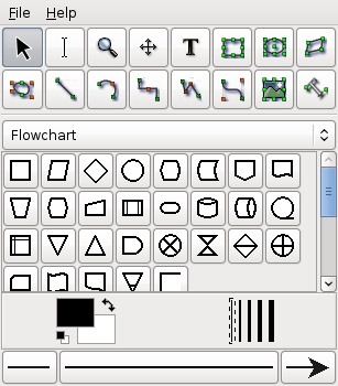
When Dia is executed, two windows open: the canvas, which contains the diagram, and the Toolbox, which contains the object palettes and other controls. The Toolbox is divided into three regions. The top region contains 14 buttons. The first three are controls used to adjust the diagram. The next 11 are the icons for the built-in basic objects.
The middle portion of the Toolbox contains the selected Special Objects. This is used to select among the many built-in object sheets supplied with Dia, such as UML, Flowchart, Network, etc.
The bottom portion of the Toolbox contains special controls that set default properties for objects placed on the canvas. These include foreground color, background color, and line width. There are also three controls that set the default properties for line objects. These are beginning arrow style, ending arrow style, and line style.

The Modify control is the default setting when using Dia. This control allows you to select one or more objects on the canvas. After an object is added to the diagram, the Modify control is automatically selected for you. This makes it easy to add an object and then continue working without having to reselect the Modify control.
![[Tip]](images/tip.png) | Tip |
|---|---|
You can toggle between an object control and the Modify control using the Space key. For example, say you wish to add several Box objects to the diagram. First, click on the Box icon and click on the canvas to add the Box. At this point, the Modify control will be selected automatically. To reselect the Box control, press the Space key. Now you can click on the canvas again to add a second Box object. Continue to press Space and then click to add as many Box objects as desired. |
| Tip |
|---|---|
You can customize Dia to disable the automatic selection of the Modify control. See Customization / User Interface for more information. |

The Textedit control is new with Dia from version 0.97 - it indicates being in text edit mode. Together with an appropriate object selection it is one way to start text modification.
An object supporting in-canvas text editing can be in two different selection modes. The normal selection is the same for all objects, it allows to manipulate the objects position, grouping etc.. Some object can enter a second selection mode, which allows to edit their text from the canvas.
| Tip |
|---|---|
There are multiple ways to enter text edit mode. You can press-and-hold the left mouse button, activate text editing by Enter or F2 key or select the respective object after activating Textedit from the toolbox. |

The Magnify control is one method for zooming in or out. See The Canvas / Zooming for more information about zooming. The Magnify control stays active until you press one of the other controls.

The Scroll control is used to move around the diagram. When this control is active, the mouse pointer changes to a hand. When the Scroll control is active, you can scroll around the diagram by clicking anywhere on the canvas and dragging the mouse. The diagram scrolls within the canvas window. The Scroll control stays active until you press one of the other controls.
After the Modify, Zoom, and Scroll controls, the next 11 buttons allow you to place Dia's basic objects on the canvas. See Basic Objects Introduction for more information on Dia's basic objects.
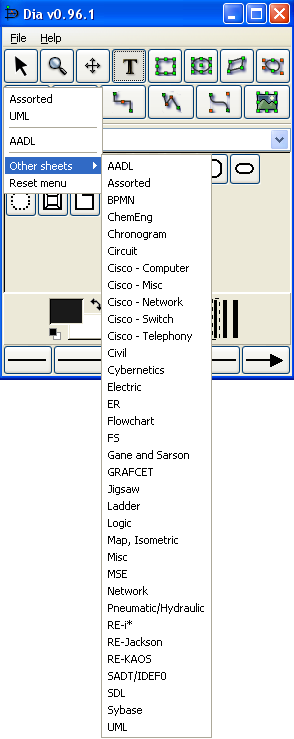
On the Toolbox, just below the basic object icons, is a drop-down listbox that allows you to select a sheet of special objects to be included in the diagram. As you can see from the screenshot above, Dia provides a large number of special objects. To use a special object, first select the desired sheet using this drop-down listbox. Then, just click on the desired object and click on the canvas to insert the object. See Special Object Categories for more information on the various types of special objects available.
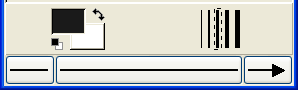
Below the special objects palette are controls for setting the default foreground and background color, line width, and line style. These controls all set default properties for new objects being added to the canvas. They do not affect the properties of existing objects already on the palette. These settings stay in effect for all future Dia sessions, until they are changed.
The two squares on the left allow you to set the default foreground and background colors for all new objects being added to the diagram. If you double-click on the upper square (i.e., the black one in the screenshot above), you can set the default foreground color for all new objects. Double-clicking on the lower square (white in the screenshot) allows you to select the default background color. See Objects / Colors for more information about selecting colors.
| Tip |
|---|---|
To set the colors back to the default, click on the black and white box to the bottom left of the color selector. |

| Tip |
|---|---|
To inverse the colors, click on the little arrow to the top right of the two boxes. |


To the right of the two squares are five lines of increasing width. To select the desired default line width, simply click on it. A dashed-rectangle indicates which width is currently selected.
At the bottom of the Toolbox are three buttons. The left button allows you to select the default arrow shape for the beginning of a line. In the screenshot this is defaulting to "no arrow". The right button allows you to select the default arrow shape for the end of a line. Since only lines have arrows, these buttons only affect line objects and have no effect on other shapes. The middle button allows you to select the default line style (solid, dashed, etc.).
![[Note]](images/note.png) | Note |
|---|---|
The line-width and line style settings affect all basic objects. For shapes, these settings determine the line properties of the shape outlines. These settings also are used for some special objects (e.g., Flowchart objects). Other special objects (e.g., AADL objects) have fixed line widths and are not affected by these settings. |
Adding objects to the Dia canvas is done by clicking on the desired object's icon button in the Toolbox and then clicking on the canvas at the desired insertion point. The selected object will be inserted at that point.
| Tip |
|---|---|
You can quickly add multiple objects of the same type to the diagram using the Space key to toggle between the Modify control and the desired object. For example, say you wish to add several Box objects to the diagram. First, click on the Box icon and click on the canvas to add the Box. At this point, the Modify control will be selected automatically. To reselect the Box control, press the Space key. Now you can click on the canvas again to add a second Box object. Continue to press Space and then click to add as many Box objects as desired. |
| Tip |
|---|---|
If you are using different colors or line styles for different objects, one trick to save time is to create a separate file of sample objects with the desired properties on a separate diagram. Then copy and paste these objects onto your working diagram as you need them. |
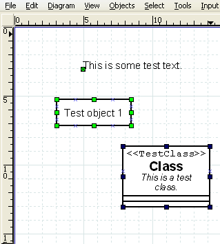
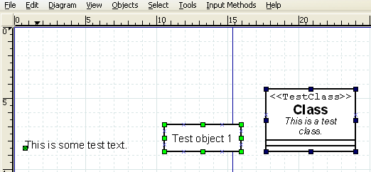
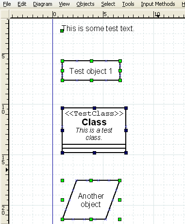
When an object is inserted into the canvas, the desired object will appear with small green boxes (known as handles) around the border.
To move an object, click anywhere inside the object (or somewhere on a line other than a handle) and drag the mouse to the desired location on the canvas. For line objects, you need to click on the line.
| Tip |
|---|---|
When moving an object, be sure not to click on a handle. Otherwise, you will resize the object instead of moving it. |
Handles are used to change the size of the object. To expand an object, just click a handle and drag it away from the center of the object. To shrink an object, drag a handle toward its center. The object's size will change as you drag the mouse. If an object has a fixed aspect ratio, changing one dimension automatically changes the other. If an object has a free aspect ratio, you can change one dimension (e.g., height) without affecting the other (e.g., width). Some objects have a property setting that determines whether the aspect ratio is fixed or free.
To delete an object, click on the object to select it. The handles will display, which indicates that the object is selected. Then press the Delete key or select -> from the menu.
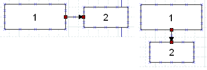
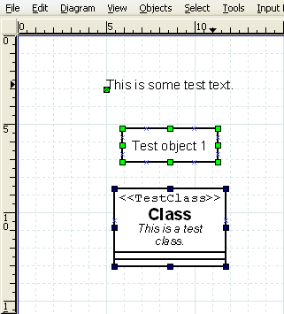
In many diagrams, shapes are connected to each other using one of the basic line objects. When a shape is not selected, a number of connection points are displayed on its borders as small "x" figures. There is also a connection point in the middle of each shape. Lines also have connection points where other lines can connect.
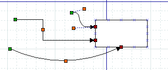
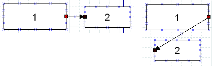
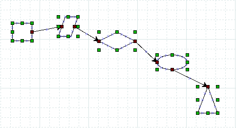
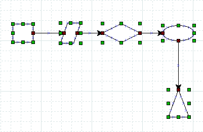
Lines have handles on each end that are used to connect them to other objects. These handles are green if the line is not connected and red if it is connected. Lines also have orange handles that are used to shape the line. The figure below shows several lines with green handles on the unconnected end and red handles on the connected end.
To connect two shapes with a line:
Select the desired line (Line, Zigzagline, etc.) by clicking on the Toolbox icon.
You can either click on the canvas to place the line on the diagram and then drag the "from" end of the line to the desired connection point of the first object.
Or you can save a step by clicking directly on the desired connection point of the first object. In this case, the line will display with the "from" end of the line already connected to the first object.
In either case, when the "from" end of the line is connected, it's "from" handle will be red.
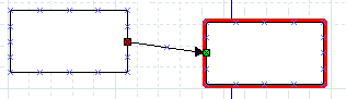
Click on green handle at the "to" end of the line and drag it to the desired connection point on the second object. When the line is connected, the outline of the object being connected will turn red, as shown in the figure below.
At this point, the two objects are connected. If you move either object, the line will stretch to keep them connected. If you move the line, it will disconnect from both objects. If you do this by mistake, you can undo using Ctrl+Z or ->.
At any time, you can disconnect or connect to a new point by clicking on the "from" or "to" handle and dragging it to a new location on the diagram.
| Tip |
|---|---|
If you connect a line to a fixed point on a shape's perimeter, it will stay connected to this point when the object is moved. If you connect a line to the middle of an object, when you move the object the displayed connection point moves automatically, so you don't need to change the connection point. Note that, when a line is connected to the middle of an object, the line's connection handle is still positioned on the perimeter of the object. So to move the line's connection point, drag on the line's handle (as opposed to the middle of the object). |
| Tip |
|---|---|
If you connect a Line or Polyline object to the middle of a shape when you first place the line on the canvas, you need to be careful when connecting the "to" end of the line. Be sure to click on the line's handle and not on the surrounding area within the shape. If you click on the surrounding area inside the shape, you will select the shape and not the line's handle. If this happens, click outside the shape to deselect it and then carefully click on the "x" in the middle of the object (not on the line's arrow). The handle will display, and you can drag it to the desired location. Note that the handle will display as red, because it is connected to the middle. Also note that you need to drag it outside the shape before you can see the line. |
See Basic Objects / Line for more information on the different lines available.
Text can be entered by selecting the object, entering text edit mode and then typing the text. The font, size, alignment, and other formatting properties can be changed by double-clicking the object, when not in text edit mode.
Many Dia objects suport in-canvas editing of text. Dia versions before 0.97 had not explicit distinction between a selected object and it's text edit mode. As a result numerous workarounds were needed to support canvas and text editing with the same set of keys, e.g. the Delete key was not deleting the character right to the cursor, but instead the whole object.
With Dia 0.97 and later there is a dedicated text edit mode. You can enter it by hitting Enter or F2 key while an appropriate object is selected. To leave text editing just click outside of the editable area or hit the Escape key.
| Tip |
|---|---|
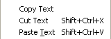
While in text edit mode the normal Copy / Paste keys (Ctrl+C, Ctrl+V) work on the entire text. The Edit menu also contains the commands Copy Text, Cut Text (Shift+Ctrl+X), and Paste Text (Shift+Ctrl+V) to copy, cut, and paste just the text contents of an object. Note that when you paste text into an object, the text is formatted according to the Dia object properties, not the text source. |
| Tip |
|---|---|
You cannot select a section of text inside an object with the mouse (this moves the cursor). You can insert characters at the current cursor position just by typing. You can delete the character to the left of the mouse using Backspace. The Del key deletes the character right to the cursor. To delete all of the text in an object, use the Cut (Shift+Ctrl+X). |
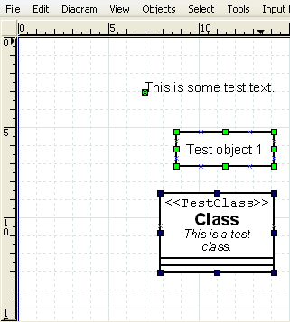
Dia provides several options to help arrange multiple objects without needing to move each object individually. These are available on the -> menu choice shown below.
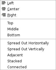
To align objects, first select the objects to align (see Selecting Objects ) and then execute one of the align commands, using either the menu or the shortcut key. The order in which objects are selected does not matter.
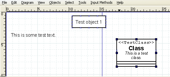
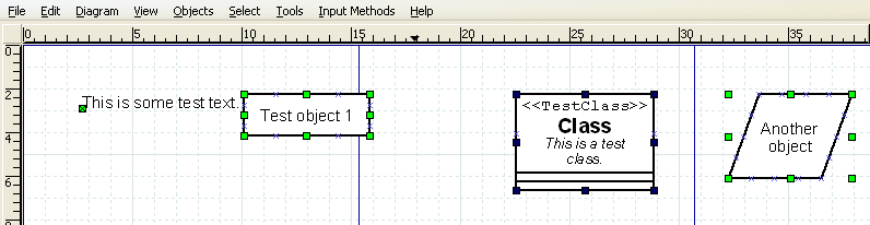
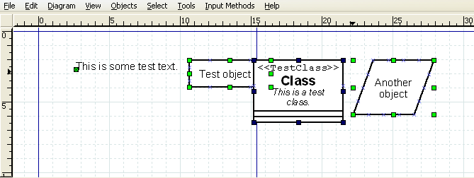
The align left, right, and center are used to align objects arranged vertically on the canvas. The align left aligns the selected objects to the left edge of the left-most object. Similarly, the align right aligns the selected objects to the right edge of the right-most object. Align center aligns the center of each object to the mid-point between the extreme left and extreme right edge of all selected objects. Examples of align left, center, and right are shown below.
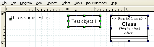
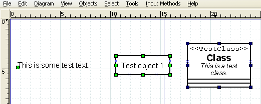
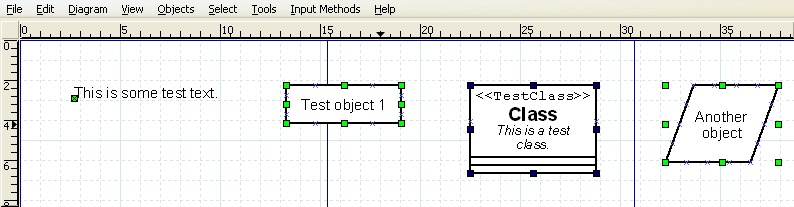
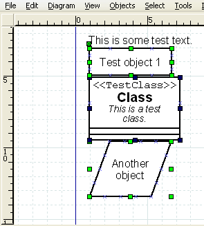
The align top, middle, and bottom are used to align objects arranged horizontally on the canvas. The align top aligns the selected objects to the top edge of the upper-most object. Similarly, the align bottom aligns the selected objects to the bottom edge of the lowest object. Align middle aligns the middle of each object to the mid-point between the extreme top and extreme bottom edge of all selected objects. Examples of align top, middle, and bottom are shown below.
The Align / Spread Out commands can be used to create uniform spacing for objects arranged either horizontally or vertically. Examples of these commands are shown below.
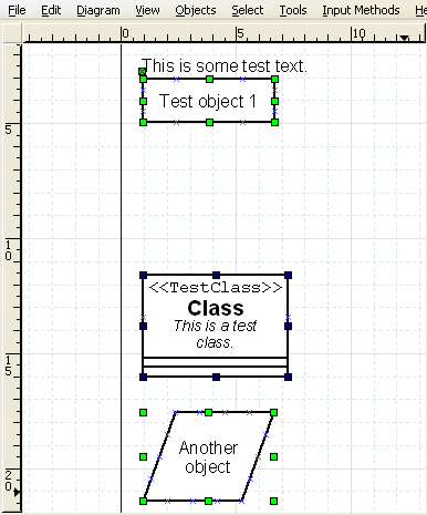
The Align / Adjacent command is used to place objects next to each other with no horizontal space in between. The Align / Stacked is used to place objects directly on top of each other, with no vertical space in between. Examples of these commands are shown below.
The Align Connected command tries to align connected objects, so that the connecting lines are either horizontal or vertical afterwards.
| Note |
|---|---|
The algorithm used to align connected objects is not fool proof, infact it is very simple. If the resulting alignment does not match your expectations use Undo to revert it. A different selection of objects may producae a result more to your liking. |
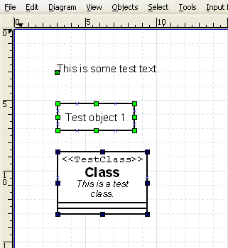
Grouping allows you to treat several objects as a single entity. A group enables you to fix the position of the member objects in relation to each other and to change the properties of all member objects at one time. To create an object group, select two or more objects and then select ->.
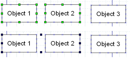
When the group is created or subsequently selected, a set of black handles displays around the outside of the group, as shown in the figure above. At this point, you can move the entire group just like you would move a single object. Just click and drag on any of the objects in the group.
You can also change the properties of all objects in a group by double-clicking or using the right-click context menu. See Changing Properties for a Group of Objects for more information.
The properties of an object control it's appearance. Properties include text font and appearance; line width, style, and color; transparency (i.e., draw background yes or no); foreground and background color; and any other settings that control the way an object is displayed. Different types of objects have different sets of properties.
The specific properties of an object are determined in two different ways. The default settings in force at the time the object is added to the canvas determine the object's initial properties. Once objects are placed onto the diagram, their properties may be set using the Properties dialog box for the object or for a group of objects.
An object's default properties are set in two places within Dia. First, as discussed above in Default Color, Line Width, and Line Style, default values for the foreground and background color; the line width; and the line style of all basic objects and some special objects are determined by settings on the Toolbox. For basic lines, the default beginning and ending arrow styles are also determined by the Toolbox settings.
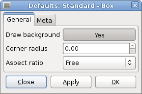
The rest of an object's default properties can be set using the Defaults: Properties dialog box for each object. This is opened by double-clicking on the object's icon on the Toolbox. Since the available properties for each type of object can be different, each object's default properties dialog is different. Below are examples of the default properties dialog for the basic Text and Box objects.
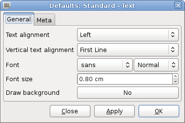
For objects that include text, the dialog will normally include the text alignment, the font name, the font modifier (normal, bold, etc.), and the font size (in centimeters, not points). This makes it possible to set defaults for text display for any object that can contain text.
Once objects are placed onto the diagram, their properties can be changed either individually or as a member of a group.
To change the properties of an individual object, either double-click on the object or select the object, right-click to display the context menu, and select the Properties option. In either case, the Properties dialog for the selected object will display, allowing you to change any of the object's properties.
| Note |
|---|---|
If multiple objects are selected, you can still change the properties of one of the selected objects by double-clicking that object. This will only change the properties of the one object you double-clicked. |
You can change the properties of a group of objects at one time by selecting two or more objects and then selecting -> to create a group. Once the group is created, you can set properties for all objects in the group. To do this, either double-click on the group or right-click to display the context menu and select the Properties option. The Properties: Group dialog will display. Only properties that pertain to all of the selected objects will display in the dialog. If your group contains only objects of one type, then all of the properties for that object type will display.
For example, if a group contains all basic Line objects, all of the Line properties will display in the Properties: Group dialog. If a group contains a basic Line and a basic Box, the Properties: Group dialog will only show Line width, Line color, and Line style, since these are the properties these objects have in common.
Changing properties for a group is a powerful feature of Dia. For example, say you have a large diagram and you need to change the line style of all the basic Line objects everywhere in the diagram. You can accomplish this easily with the following steps.
- Select one basic Line object.
- Use -> to select all of the basic Line objects on the diagram.
- Use -> to create a group for the selected objects.
- Double-click on the group and make your property changes.
- Use -> to remove the group.
All objects in Dia have color attributes. Lines have line color. Shapes have line color and fill color. Text and other objects that contain text have text color. In addition, the -> allows you to set colors for Background, Grid Lines, and Page Breaks. Finally, the Toolbox allows you to set default foreground and background colors for new objects.
In most cases, there are two methods for selecting a color. First, you can select a color from a list of colors provided in the drop-down listbox by each color property.
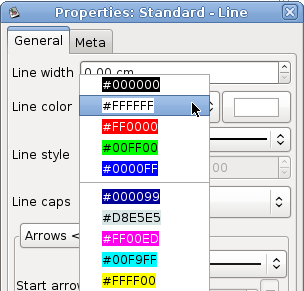
The list contains five primary colors (black, white, red, green, and blue) plus custom colors that have been previously used. You can just select a color from the list or select "More colors..." to display the Select color box. The Select color box allows you to select any color. It is explained in the next section.
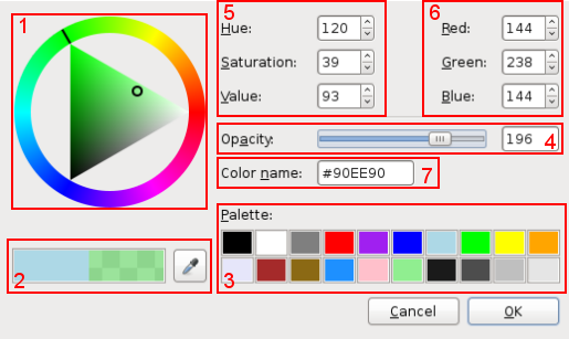
The Colors selector box contains 7 zones:
The colors wheel allows you to select a color using the mouse. Select the color you want from the outer ring. A white or black line shows the current position on the ring. Select the darkness or lightness you want using the inner triangle. A white or black circle shows the current position in the triangle. You can click or drag on either surface. The currently-selected color displays in the right side of the rectangle just below the circle.
Below the color wheel there are two rectangles. The left one displays the current color of the object, the right one the new color (i.e., the one you currently have chosen using the colors wheel). Pressing the OK button will set the object to the new color.
Just to the right of these rectangles, there is a pipette button. When you click this button, the mouse pointer changes to a pipette. When the pipette is active, you can click on the canvas or any open application window (Like The Gimp), and select any color!
Note On Windows, you can only select from colors on the Dia canvas.
In the lower right there is a predefined color palette. Click on any of these to choose the color.
To control the transparency of the color you can use the slider in the middle right.
In the upper center there are settings for Hue, Saturation, and Value (HSV). You can select a color by typing a numeric value or by using the increment / decrement controls. Note that when you enter a value here, the color wheel selection changes to reflect the new color.
To the right, there are settings for Red, Green, and Blue. These work the same as the HSV controls.
In the middle of the box is a place to enter a Color name. This supports standard color names or HTML-style hexadecimal color values. (See HTML4.01 colors on http://www.w3.org), and hexadecimal values (0-9A-F) on 3 or 6 octets.
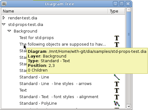
The Diagram Tree provides an alternative method of working with a diagram. This window displays a list of all objects in the diagram in a scrolling list box. By right-clicking on an object, you can perform a number of operations.
The Diagram Tree is toggled on or off by selecting -> from the Toolbox menu bar or by pressing F8 when the Toolbox is in focus.
Some actions on the Diagram Tree affect the diagram itself. By selecting objects in the tree, you can modify multiple of them at once. You can sort the objects in the tree by type or name. click on the respective table header. If you right-click on the Diagram Tree list, a context menu displays with three options.
These options are explained below.
Select will transfer the current the selection in the tree to the diagram.
Locate will bring the selected object(s) into view on the canvas. This can be useful if you are trying to find an object in a large diagram.
Properties will display the properties dialog for the selected object(s). See Object Properties for more information.