- 6.1.1. Special Object Categories
- 6.1.1.1. Assorted
- 6.1.1.2. Chemical Engineering
- 6.1.1.3. Chronogram
- 6.1.1.4. Circuit
- 6.1.1.5. Cisco - Computer
- 6.1.1.6. Cisco - Misc
- 6.1.1.7. Cisco - Network
- 6.1.1.8. Cisco - Switch
- 6.1.1.9. Cisco - Telephony
- 6.1.1.10. Civil
- 6.1.1.11. Cybernetics
- 6.1.1.12. DIN Electrical
- 6.1.1.13. ER
- 6.1.1.14. Flowchart
- 6.1.1.15. FS (Function Structure)
- 6.1.1.16. GRAFCET
- 6.1.1.17. Istar
- 6.1.1.18. Jackson
- 6.1.1.19. KAOS
- 6.1.1.20. Map 3D Isometric
- 6.1.1.21. Misc.
- 6.1.1.22. MSE
- 6.1.1.23. Network
- 6.1.1.24. PLC Ladder
- 6.1.1.25. Pneumatic/Hydraulic
- 6.1.1.26. SADT
- 6.1.1.27. SDL
- 6.1.1.28. Sybase
- 6.1.1.29. UML
- 6.1.2. Organizing Sheets and Objects
Special objects are sets of objects designed to serve specific needs. They are organized into categories called sheets. The middle section of the Toolbox allows you to select a sheet of special objects. When you do this, the objects on this sheet display on the Toolbox and can be added to your diagram just like basic objects. Dia supports numerous predefined categories.
The predefined sheets are designed to group related objects together so you can see all of the objects you are likely to need on the same sheet. However, it is easy to modify the predefined sheets. See Organizing Sheets and Objects for more information.
It is also possible to create your own objects and sheets without programming. Custom shapes can be created with an XML file that describes the shape. See Custom Shape Module for more information on custom shapes.
- 6.1.1.1. Assorted
- 6.1.1.2. Chemical Engineering
- 6.1.1.3. Chronogram
- 6.1.1.4. Circuit
- 6.1.1.5. Cisco - Computer
- 6.1.1.6. Cisco - Misc
- 6.1.1.7. Cisco - Network
- 6.1.1.8. Cisco - Switch
- 6.1.1.9. Cisco - Telephony
- 6.1.1.10. Civil
- 6.1.1.11. Cybernetics
- 6.1.1.12. DIN Electrical
- 6.1.1.13. ER
- 6.1.1.14. Flowchart
- 6.1.1.15. FS (Function Structure)
- 6.1.1.16. GRAFCET
- 6.1.1.17. Istar
- 6.1.1.18. Jackson
- 6.1.1.19. KAOS
- 6.1.1.20. Map 3D Isometric
- 6.1.1.21. Misc.
- 6.1.1.22. MSE
- 6.1.1.23. Network
- 6.1.1.24. PLC Ladder
- 6.1.1.25. Pneumatic/Hydraulic
- 6.1.1.26. SADT
- 6.1.1.27. SDL
- 6.1.1.28. Sybase
- 6.1.1.29. UML
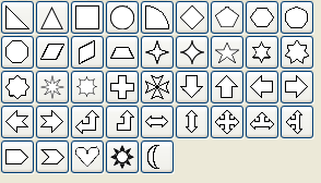
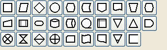
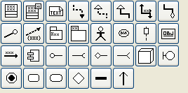
Assorted Geometric Shapes. The purpose of this sheet is to provide a selection of simple and convenient preset shapes so that users need not create spend time creating their own basic shapes. The set includes shapes with constrained ratio such as perfect Circles, Squares, various type of Triangle and Crosses. These objects do not allow text to be entered inside the shape.
A collection of shapes for modeling the process of Chemical Engineering.
Uses objects to be used in a chronographic design. These are common place in time lines.
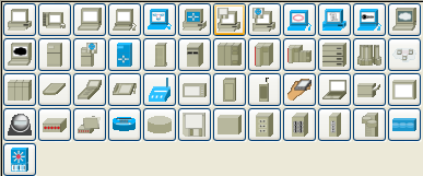
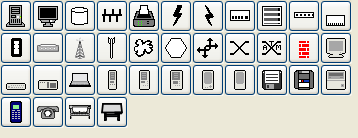
Cisco - Computer includes shapes representing computer equipment from Cisco, a manufacturer of Computer Networking Equipment.
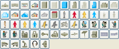
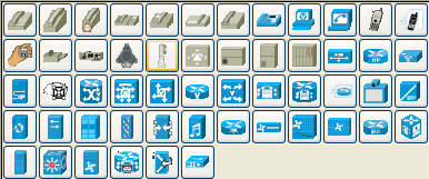
Cisco - Misc includes miscellaneous shapes from Cisco, a manufacturer of Computer Networking Equipment.
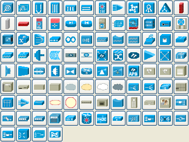
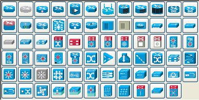
Cisco - Network includes shapes representing network equipment from Cisco, a manufacturer of Computer Networking Equipment.
Cisco - Switch includes shapes representing switch equipment from Cisco, a manufacturer of Computer Networking Equipment.
Cisco - Telephony includes shapes representing telephony equipment from Cisco, a manufacturer of Computer Networking Equipment.
DIN style electrical control schematics (electrical controls in manufacturing automation).
Editor for Entity Relations (ER) Diagrams. Entity Relationship diagrams are used to represent high level descriptions of conceptual models in terms of how each data entity relates to other data in the model. They are most commonly used to model the structure of data to be stored in a database.
A group dedicated to providing the user shapes which are commonly used in flow charts. Flow charts can be routinely found in computer programming, marketing, economics, and any other semi-linear operation which requires planning. Most flowchart objects allow entry of text.
Editor for Function Structure (FS) Diagrams. Note that the Objects require the use of the context menu to access much of the functionality of these objects.
Grafcet (or IEC 61131-3 SFC) diagrams. Used in graphical programming and documenting sequential processes in manufacturing automation.
A chart shows the step, the action, the transition, and the condition associated with the transition.
Pseudo 3D isometric shapes for creating Directional Maps. Microsoft Visio calls these shapes Map, Directional Map 3D.

Miscellaneous shapes that do not fit into any of the other groups. Includes some File system shapes and an animated clock object that updates in real time.
Used by network administrators to create a design of their network.
PLC 'Ladder' graphical programming (electrical controls in manufacturing automation).
Specification and Description Language (SDL) SDL is used to describe the behavior of interactive time based systems. SDL was originally focused on telecommunication systems, but has also come to be used to describe process control and real-time applications in general.
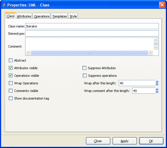
Unified Modeling Language (UML). UML is a modeling and specification language commonly used to create diagrams showing the structure of object-oriented computer programming code, particularly for large scale projects. Some UML objects are complex and have extensive properties for various types of text entries, as shown in the screenshot below.
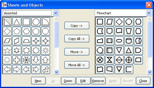
It is possible to modify the way objects are grouped into sheets. Say, for example, that most of the object you need are on one sheet but you also need some objects from a second sheet. To keep everything you need on one sheet, you can copy objects from one sheet to another as follows:
On the Toolbox menu, select ->. This will display the dialog shown in the figure below.
Using the drop-down listbox on the left side, select the sheet you want to copy from. On the right, select the sheet you want to copy to.
Click on the object you wish to copy on the left side and press the Copy button.
Repeat for any other objects you want to copy. When you are done, press the Apply button on the bottom to save your changes.
From now on, the new objects will be listed on the sheet on the right. You can also remove objects from sheets and move objects from one sheet to another. You can also use the Up and Down buttons to change the order of the objects within a sheet.