Dia allows you to set a number of customization options that modify how the program works. These options are set by selecting the -> from the Toolbox Menu Bar. This opens the Preferences dialog. This dialog has tab panes grouping related preferences like: User Interface, Diagram Defaults, View Defaults and Grid Lines.
After you have made all the changes you want, click on to apply the changes and close the Preferences dialog. To cancel the changes and return to previous values, click the button. You may preview the effect of your changes using the Apply button.
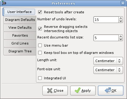
The User Interface tab pane allows you to change the way Dia works. The configurable properties in the User Interface tab are explained below.
Reset tools after create causes the Modify tool to be selected automatically each time an object has been added to the diagram. This allows you to add an object and then use the Modify tool to select objects without having to go back to the Toolbox.
If the Reset tools button is not checked, then the current object tool will "stick" until another tool is chosen. This is useful if you want to draw many shapes using the same tool repeatedly. However, in this case, you will need to manually select the Modify tool in order to select objects.
![[Tip]](images/tip.png)
Tip As an alternative to unchecking this box, you can press the Space key after inserting an object to reselect the last object. See Adding Objects for more information.
Compress saved files provides the option to have Dia XML files compressed into much smaller files using gzip or to leave the Dia XML files as plain text so that they can be more easily edited using other software.
Number of undo levels customizes how many steps that the undo tool remembers. The higher the number, the more steps you can undo to fix an error. However, more undo levels requires more computer memory. Setting the undo level to zero allows the program an unlimited number of undo levels, subject to the available computer memory.
Reverse dragging selects intersecting objects allows you to create selections by area that only need to cover part of the object you want to select. Normally when you select objects by area, you need to create a selection around the whole of the object you want to select in order to select it. Also, normally dragging from the top-left to the bottom-right is the same as "reverse dragging" -- dragging from the bottom-right to the top-left.
If this option is checked, dragging from the bottom-right to the top-left allows you to select objects that only partially fall into the selection rectangle. Dragging from the top-left to bottom-right still works the same -- objects are only selected if the whole object is inside the selection rectangle.
This option gives you two different ways to select by area, depending on which way you drag the mouse.
Recent Documents list size allows you to set how many items will be shown in the Recent Documents section of the menu.
When Use menu bar is checked, the pull-down menus appear at the top of each Diagram, and the object context menus are accessed by right-clicking on a selected object. If this box is unchecked, these menus do not display at the top of the diagram. Instead, these menus are selected by right-clicking on the canvas, and the object context menus are selected by middle-clicking (on a three-button mouse) on a selected object.
![[Note]](images/note.png)
Note If you do not have a three-button mouse, you will need to have this box checked. Otherwise, you will not be able to access the object context menus.
Keep tool box on top of diagram windows ensures that the Toolbox window is always in front of all the diagram windows which makes it easier to keep track of and have quick access to the tool at all times.
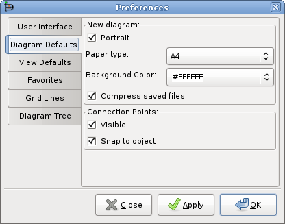
The Diagram Defaults tab allows you to set default properties for all new diagrams. These are explained below.
Portrait indicates that the diagram is in portrait orientation on the page. If this is unchecked, then landscape orientation is assumed.
Paper type allows you to select from a list of paper sizes (e.g., A4, Letter, etc.).
Background color allows you to set a default background color for all new diagrams. See Colors for more information on setting colors.
New Window: Width allows you to set default width (in pixels) of the window when a new diagram is created. You can either enter a number manually or use the increment / decrement buttons.
New Window: Height allows you to set default height (in pixels).
New Window: Magnify allows you to set the default zoom value (in percent) for a new diagram. You can either enter a number manually or use the increment / decrement buttons.
Connection Points: Visible determines whether connection points will be visible by default on new diagrams. When working with a diagram, this can be toggled on or off using the -> on the Diagram menu bar.
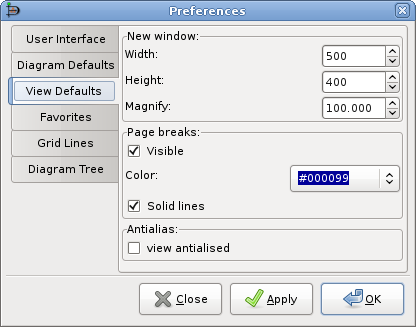
This tab allows you to set default properties for the Page break lines.
Page Breaks: Visible controls whether page break lines will be visible.
Color allows you to select the default color of the page break lines. This can be changed for a single diagram using the Colors tab on the -> menu choice from the Diagram menu bar.
Solid lines determines whether the page break lines appear as solid lines or as dashed lines.
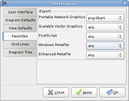
When exporting files there are often multiple filters capable to save to one format. This preference allows to choose the one used, when not explicit selected in the file export dialog, i.e. gets used.
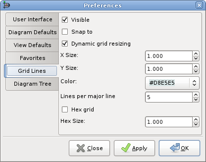
This tab allows you to set default properties for Grid Lines. These may be changed for an individual diagram by selecting the -> from the Diagram menu bar and then selecting the Grid tab. These options are explained below.
Visible determines whether, by default, grid lines will be visible on new diagrams.
Snap to determines whether, by default, new diagrams will have snap-to-grid enabled. Snap-to-grid forces object edges to move to the nearest grid line intersection. This makes it easier to align objects, as separate objects snap to the same line. This feature can be toggled on or off using the snap-to-grid button on the bottom of the Toolbox. See Canvas / Grid Lines for more information. This can also be toggled using the -> option on the Diagram menu bar.
Dynamic grid resizing determines whether the grid size changes as the diagram is zoomed in or out. If this box is checked, then the grid lines display as the same size no matter how the diagram zoom is changed. In this case, the X Size and Y Size values have no effect.
If this box is unchecked, then the grid size is set in absolute terms according to the X Size and Y Size values (in centimeters). In this case, the appearance of the grid will change as the zoom changes, so the grid lines will move closer when you zoom out and will spread out as you zoom in.
X Size determines the distance, in centimeters, between grid lines along the horizontal axis. This only takes effect if Dynamic grid resizing is unchecked.
Y Size determines the distance, in centimeters, between grid lines along the vertical axis. This only takes effect if Dynamic grid resizing is unchecked.
Color sets the display color of the grid lines.
Lines per major line determines the spacing of major (i.e., solid) grid lines. For example, a value of 5 means that every 5th grid line is solid.
Hex grid allows you to have a grid of hexagons instead of a rectangular grid.
Hex size determines the size of the hexagons, in centimeters, in the hex grid. This option only applies if Hex grid is checked.