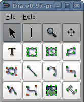
Dia has a dozen basic objects: Text, Box, Ellipse, Polygon, Beziergon, Line, Arc, Zigzagline, Polyline, Bezierline, Image and Outline.
Dia supports the use of text as its own type of object. Text can be placed on the canvas by clicking on the text button on the toolbox. For tips on editing text, see Entering Text in the Using Objects chapter.
![[Note]](images/note.png) | Note |
|---|---|
Text in Dia can use almost any font available in the system. But if you plan to exchange diagrams with people using a different plattform, it would be smart to restrict yourself to a common subset. |
The text object, and several other objects, offers direct text entry in the diagram. Text can be entered by selecting the object and then typing the text. The font, size, and other formatting properties can be changed by double-clicking the object.
Here are some important tips regarding short-cut keys when entering text.
The normal Copy / Cut / Paste keys (Ctrl+C, Ctrl+X, Ctrl+V) don't work for text. They work for entire objects. Use Ctrl+Shift+X to cut and Ctrl+Shift+V to paste just the text in an object. There is no shortcut to copy just the text.
Note When you paste text into an object, the text is formatted according to the Dia object properties, not the text source.
You cannot select a section of text inside an object with the mouse (this moves the object). You can insert characters at the current cursor position just by typing. You can delete the character to the left of the mouse using Backspace.
Note The DEL key used to delete the entire object, now it should work as expected: it either deletes the object or the text to the right of the cursor depending on the editing mode. If you delete something (text or object) by accident use ->or Ctrl+Z if you delete an object by mistake.) To delete all of the text in an object, use the Cut (Ctrl+Shift+X).
If you are using a non-default font or font size, one trick for productivity is to create a palette of empty objects with the desired font settings on a separate diagram. Then copy and paste these objects onto your working diagram as you need them (i.e., instead of using the Toolbox icons).
The boxes in Dia can be customized to be any size desired by the user. The properties available are:
Corner Rounding - Causes the corners to be rounded instead of hard edges.
Draw Background - Keeps the center clear or fills with the background color.
A polygon is any closed shape made up of straight lines. The polygon tool, allows the user to draw any shape with all straight lines.
A beziergon is similar to the polygon as the user defines the shape. However, it differs in that it allows curves to exist in the shape.
A Line is a simple straight line. Unlike the other lines, the simple Line does not have any handles to allow the shape to be altered. It just has two connection handles, one at each end.
An Arc is a line which has been bent to create a semi-circle shape. Drag the orange handle in the middle to alter the curve of the arc.
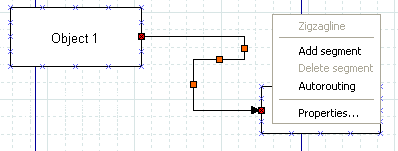
A Zigzagline is a line which has sharp, 90 degree turns in it. Zigzaglines have two special properties, Corner radius and Autoroute. Corner radius allows you to round the corners of the line. On the Properties page, enter a number between 0 and 10.00, where 0 = square corners and 10.00 = maximally-rounded corners.
Autoroute is a yes/no property. If yes, the line is automatically routed between the start and end points with the minimum number of segments. If you move or change the shape of the line, the Autoroute property is automatically set to no. Autoroute can be set on the Properties page or using the right-click menu.
Zigzaglines also allow you to add or delete line segments. This can be useful if you need the line to turn several corners (e.g., to traverse around some other objects) or to get the arrow pointed in the right direction. To add or delete a segment, right-click on the line at the point on the line where you want to add or delete and select Add segment or Delete segment.
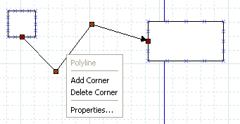
A Polyline has multiple segments like a zigzagline, but can have turns of any angle. A Polyline starts with one segment. You add more segments by right-clicking and selecting Add segment from the menu. Like the Zigzagline, the Polyline has a Corner radius value between 0 and 10.00, where 0 = sharp corners and 10.00 = maximally-rounded corners.
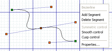
A Bezierline is a line which has curves in it. The Bezierline's shape is edited by clicking and dragging the green and orange dots. The green dots customize the size while the orange dots customize the angles at which the line curves. With a right-click menu, you can add or delete segments. If you add one or more segments, three additional properties are available.
Symmetric control causes any dragging action on the added segment to be symmetrical around this point.
Smooth control allows you to pull away from the middle point independently but rotations around the middle point are symmetrical.
Cusp control allows you to drag each handle independently, and actions on one handle have no effect on the other one.
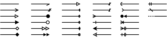
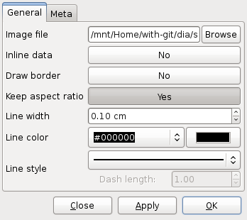
All lines share the following properties: width, color, style, and arrows. These properties may be edited using the Properties dialog box shown below.
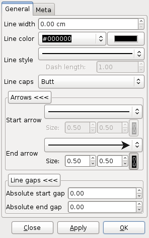
The line width is measured in centimeters and can be entered manually or by using the increment / decrement buttons.
Line colors are edited by opening the Line color drop-down listbox and either selecting one of the choices on the list or "More colors...", which opens the Select color dialog. To change transparency you can also use the color button to the left of the color drop-down listbox. See Colors for more information on selecting colors.
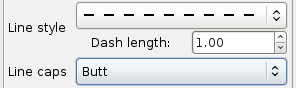
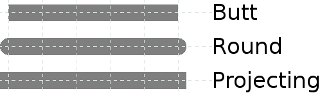
The style of the line (solid, dots, etc.) can be changed by using the Line style drop-down listbox. If you select a line style with dashes, you may also enter a dash length, measured in centimeters. The line caps can be changed by the respective combobox.
A diagram can contain images as well as shapes. To add an image, click on the Image icon and click on the canvas. An object that says "Broken Image" will appear. Double-click it to open the properties dialog. Then click on "Browse" and select your file. Click "OK" and then the image will display on the diagram. You can resize the image as desired using the object handles.
The following image are usually supported for inclusion in Dia diagrams:
- BMP
- JPEG
- PNG
- SVG
- XPM
With Dia 0.98 there is an additional way to create image shapes. Choosing -> will either update the image data in a selected image object or create a new image object contaioning the content of the clipboard.
![[Tip]](images/tip.png) | Tip |
|---|---|
Images can be stored embedded in the diagram ("inline data"). You should handle this option with care, because embedding images increases not only the files size, but also the load and save times for the diagram. |
One of the most requested features for Dia is rotated text; shortly before having transformation capabilities for everything ;-) The Outline object is a small step in that direction. It has known limitations in convenience (you need to open the properties dialog to change the text) and rendering style Dia's drawing model does not allow to render holes) with all supported renderers.