The Dia Quickstart is designed to help you get started creating diagrams with Dia without having to read a manual.
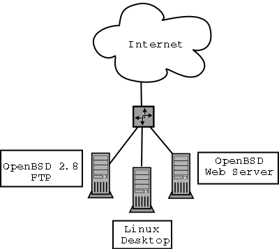
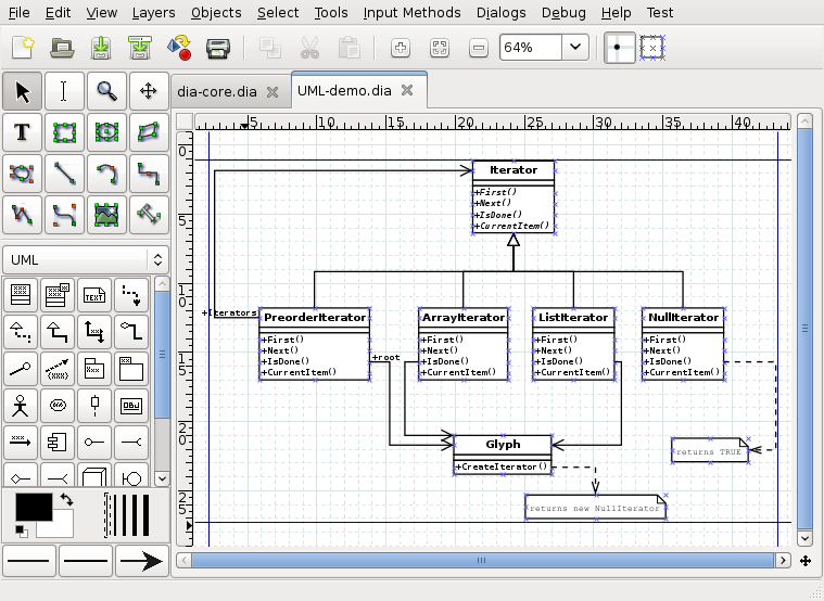
Dia is a diagramming application that can be used to make a large variety of diagrams. Dia is easy to learn and flexible enough to allow power users to create highly customized diagrams. Below are two simple examples of diagrams that can quickly be created using Dia.
You can start Dia by going into the Applications section on the Main Menu and clicking on the Dia icon. Or, you can type dia in a console window or xterm.
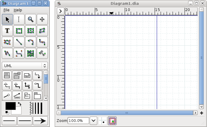
All diagrams are drawn in their own canvas. When you first start Dia, a blank canvas is created automatically. At any time, you can create a new canvas by selecting -> The canvas may be customized in various ways, such as changing the background color or grid lines. See The Canvas for more information on customizing the canvas.
A diagram is made up of objects. Objects are shapes or lines that can be different colors and sizes. Objects can be simple line drawings, text, or full-color pictures. Some objects allow text to be entered inside the shape.
Using Dia to create a diagram is easy. The Toolbox contains a palette of predefined objects, including simple shapes, lines, and specialized objects. To add an object to the canvas, simply click on the desired object's icon on the Toolbox and then click on the desired point on the canvas. The object will appear on the canvas where you clicked. See Adding Objects for more information.
An object can be moved by clicking on the object and dragging the mouse. The object can be resized by clicking and dragging one of the object's green or red "handles". See Moving Objects and Resizing Objects for more information on moving and resizing objects.
Objects can be connected using lines. Just drag each end of a line to any connection point (small blue "x") on an object. Once objects are connected, they can be moved and the line stretches to keep them connected. See Connecting Objects With Lines for more information on how to connect objects.
In the Toolbox, you can double-click on any object's icon to view and edit the object's default properties. This allows you to customize various default properties of each object. For objects that include text, you can customize the text alignment and font properties. For standard shapes, you can customize the transparency, the corner shape, and the aspect ratio. See Sources of Default Properties for more information about changing default properties.
Dia includes a set of standard shape and line objects. See Objects for more information on working with the standard objects. Dia includes a large number of predefined objects for various uses. These include flowcharts, UML diagrams, network diagrams, and many others. See Special Object Categories for more information on the various objects available.
Many common tasks in Dia require selecting one or more objects. Dia includes a number of ways to select objects quickly. See Selecting Objects for more information.
Dia can be customized in a number of ways. See Customization for more information on customization.
Layers create multiple-images so they are one image. By doing this, a user can edit one layer without worrying about affecting any of the other layers. See Managing Layers for more information on working with layers.
Dia is designed to make adding new user-defined shapes very easy. See Custom Shape Module for more information on creating your own custom shapes.
Dia provides the normal save and print options, located on the File menu. Selecting the -> allows you to set the paper size, orientation, and print margins. This also allows you to choose whether to print the diagram to scale (entered in percent) or to fit the diagram to a specific size (in centimeters).
Dia supports exporting to numerous formats for excellent web publishing. Some of them include:
- Computer Graphics Metafile (.cgm)
- Encapsulated Postscript (.eps)
- Portable Document Format (.pdf)
- Portable Network Graphics (.png)
- Scalable Vector Graphics (.svg)
See Loading and Saving Diagrams for more information.
![[Note]](images/note.png) | Note |
|---|---|
On some Windows systems, Dia diagrams do not print correctly. This problem can be worked around by exporting the diagram -- for example to Portable Networks Graphics (.png) format -- and then printing the exported .png file. |
Dia can be run from the command line. This allows certain Dia capabilities to be used in batch script files. See Dia Command Line for more information on creating your own custom shapes.
Dia can be used by many people in a variety of industries.
A systems engineer can create SADT diagrams for system analysis and design.
A requirements engineer can compose e.g. RE-KAOS, RE-Jackson or RE-I* diagrams.
A software developer can create UML diagrams of various types and extend them with the flexibility of a general purpose diagram tool.
A database designer can represent data relations with ER diagrams.
A control engineer may draw Cybernetics diagrams.
A computer programmer can create a flow chart to show the execution path of a program.
A network administrator can create a diagram to model the company's company network.
An electrical engineer may use Dia to create a diagram to show how a circuit works.
An mechanical engineer may design some Hydraulic or Pneumatic diagrams.


